CANNON Polyurethane Technology
TABLE OF CONTENTS
Following material taken from original Cannon Manual.
Any section will be provided upon request.
1.0 Technical Description and Theory
2.0 Open
3.0 Machine Specifications
4.0 Installation and Startup Information
§ Pre-Startup Information –Installation Requirements
§ Startup Procedures
§ Calibration Procedures
5.0 Maintenance / Troubleshooting Description of operation
6.0 Machine Controls
§ IRD Controller Manual
§ Control Panel
§ PLC Interface
§ PLC Program
7.0 Wiring Diagram
Chemical Flow Control
§ FPL 14 with Adjestable device Mixhead
§ DN-16 Diverter Valve
9.0 Rexroth A2VK12 Metering Pumping System
10.0 Rexroth Mixhead Hydraulic Unit
11.0 Tank Group
12.0 Cannon Supplied Optional Equipment
13.0 Auxiliary Equipment
§ Thermal Care Accuchiller – Air cooled 5 ton
§ Cuno Self Cleaning Filter
14.0 Assorted Engineering Drawings
§ Control Panel Assembly
§ Metering Machine and Tank Flow Schematics
§ General Metering Machine Arrangement
§ Tank Group Drawings
§ Metering Machine Bill of Materials
15.0 Suggested Spare Parts Listing
General Machine Description
A-20 Standard Controls
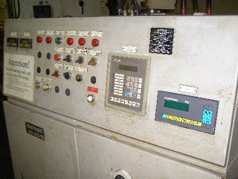
A self-contained control panel will be mounted on the metering unit frame and will contain the following items:
Upper Control Panel
Cincinnati operator interface keypad I.R.D.
Chemical temperature controllers
Lower Control Panel
· SLC 5/02
· Low suction pressure indicator
· High outlet pressure indicator
· Low hydraulic pressure indicator
· Power control switch
· Metering pump start button
· Hydraulic unit power switch
· Cycle selector switch
· Emergency stop button
· Metering pump stop button
· Calibration switch
· Reset button
Wet System General Specification
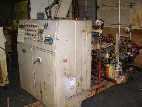
One (1) CANNON USA A-100 Standard high pressure metering machine is designed to process a two (2) component, unfilled polyurethane system. Metering is a accomplished by two (2) Rexroth positive displacement axial piston pumps driven by one (1) induction motor. Temperature conditioning is by means of shell and tube heat exchangers and jacket day tanks fitted with electrical immersion heaters and cooling water demand solenoids.
Each component is stored in 87 gallon tanks. The tanks are pressurized with dry air. Each chemical flows by "blanket" pressure from the tank through an inline component filter to the metering pump.
Mixing is by the impingement principle with a hydraulically operated self-cleaning mixhead. The hydraulic power is supplied from a self contained hydraulic power unit complete with pump, motor, reservoir and heat exchanger. The hydraulic power unit is mounted on the metering frame. The hydraulic head actuation is controlled by double hydraulic valves.
Monitoring of each component flow rate and ratio of the components is accomplished by the I.R.D (Instant Ratio Detector). The flow rates and ratio of the components is measured by means of high precision flow transducers mounted between the metering pumps and diverter valves.
Process Data Based on original Chemical Data
Output (1.0 S.G., 1:1 ratio) 600/1200 rpm 6.0 TO 59 lbs/min
@1:1ratio @1.0 S.G.
Ratio 5:1 –1:1 – 1:5 Stepless Adjustment,@1.0 S.G.
Process Temperature 80-90 degree F 80-90 degree F
Metering Accuracy +/- .05%
Component +/- 2 degree f.
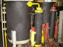
Work Tank Specifications
Chemical components are stored in pressurized tanks. Chemical conditioning in the tank is achieved with electrical resistance heaters located at the bottom of each tank, and with the use of external chilled water.
Four Capacitance level controls are mounted on the tank to control replenishment of materials form customer's drum stock or bulk storage plant and to signal for high and low level alarms.
Specifications
§ Reservoir capacity: 87 gal ea.
§ ASME Pressure rating:150 PSI
§ Component heating capacity: 3 Kw each
§ Component cooling capacity: 5 ton air cooled chiller
§ Capacitance levels: Full range with full indicator ( levels per tank)
§ Air requirements: 90-120 psi regulator.
§ Poly Heat Exchanger Shell and tube exchanger.
§ ISO Heat Exchanger Shell and tube exchanger.
§ Water flowRequirements: 25GPM
Metering Machine Specification
The CANNON USA A-20 STANDARD comprises a high pressure metering unit utilizing positive displacement axial piston pumps to generate high pressure mixing.
A-20 STANDARD Specification
- Output @ 1.0 S.G., 1:1 ratio 438 gram/sec @ 900 Rpm
876 gram/sec @ 1800 Rpm
- Ratio adjustment 5:1-1:1-1:5 stepless
adjustment @ 1.0
specific gravity
- Metering Accuracy +/- 0.5%
- Component Heating 3.0 Kw/component
- Component Cooling By Customer
- Motor Size 10 Hp
- Pump Size, Poly A2VK12 Rexroth
- Pump Size, Iso A2VK12 Rexroth
- Temperature Control Shell & Tube heat
exchanger
- Filter Self cleaning Cuno
- Mixhead Hydraulic Unit 7.5 Hp, 2.6 Gpm
- Power Requirement 460 V, 60 Hz, 3
phase, 100 Amp
service
Air Requirement 90-120 Psi
Water Flow Requirement By Customer
Instant Ratio Detection System
Cincinnati Electrosystems Greyline 2000 Series Workstation.
Piping Manifold Specification
The manifold system consist of the framework, piping, fittings, valves and conduit, which provides the pressurized delivery of the chemical components, hydraulic fluid and electrical signals to one (1) FPL-14 mixing heads.
The manifold will consist of the following:
- Floor mounted support frames
- High pressure carbon steel seamless tubing for feed and return of the chemical components and hydraulic fluid.
- Tubing insulation for chemical lines
- Dual mixhead hydraulic valves
- Accumulator for mixhead hydraulic system
- Pressure guages
- Electrical raceway
- Electrical junction box
FPL Mixhead
The FPL mixhead is mechanically self-cleaning high pressure mixhead capable of free pour, open mold dispense or fixed to a closed mold for injection.
The FPL mixhead has two (2) chambers, the mix chamber and the output chamber. Each chamber has its own clean-out piston. The mix chamber is located at a 90 degree angle to the outpour chamber. The sequence of movement during a shot is as follows:
1. Cleanout chamber piston retract - beginning of pour.
2. Mix chamber piston retract pouring occurs
3. Mix chamber piston closes pouring stops
4. Cleanout chamber piston closes -end of pour
Specifications
Minimum total components output @ 1:1 ratio:
100 cc/sec total (both components)
Maximum total components output @ 1:1 ratio:
600 cc/sec total (both components)
Component maximum working pressure: 3000 Psi
Mixhead Hydraulics
The mix piston and cleanout piston movements are controlled hydraulically. The operation of each piston is controlled independently from the other by the use of a double hydraulic valve set-up. Each piston is fitted with a proximity sensor for detection of the piston in the open position.
Electrical Requirements
Electrical Power: 460V, 60Hz, 3 Phase
Service Amps: 100A
450A main disconnect (to service entire system)